Bi-Weekly 135 Update; Week #2-3
With the wintery season, we were not able to have sufficient content last week. So, we shall have a joint week update.
The Infinite Monkey Theorem (turret)
A bunch of students spamming turret ideas is bound for greatness. Or something.We’ve made a pretty major pivot on our turret design. The whole goal was to make dual turrets actually viable strategically (big hopper / high throughput) while still fitting inside our packaging constraints.
Originally, we were aiming for <180° of motion, but we realized we wanted at least 360° rotation. So, with our packaging, that means we have to fit all of the rotating assembly on top of the turret within a 12” circle.
But there are a few problems we need to contend with in this area:
- A Kraken X60 is about 4.4” long front-to-back and, obviously, 60mm OD
- The center ball hole needs to be ~6.1” in diameter, so that the game piece has clearance
That leaves under ~3” of annular space (around the ball hole) to fit everything:
- hood
- flywheel
- motor(s)
- power transmission/encoding
- structure/mounting
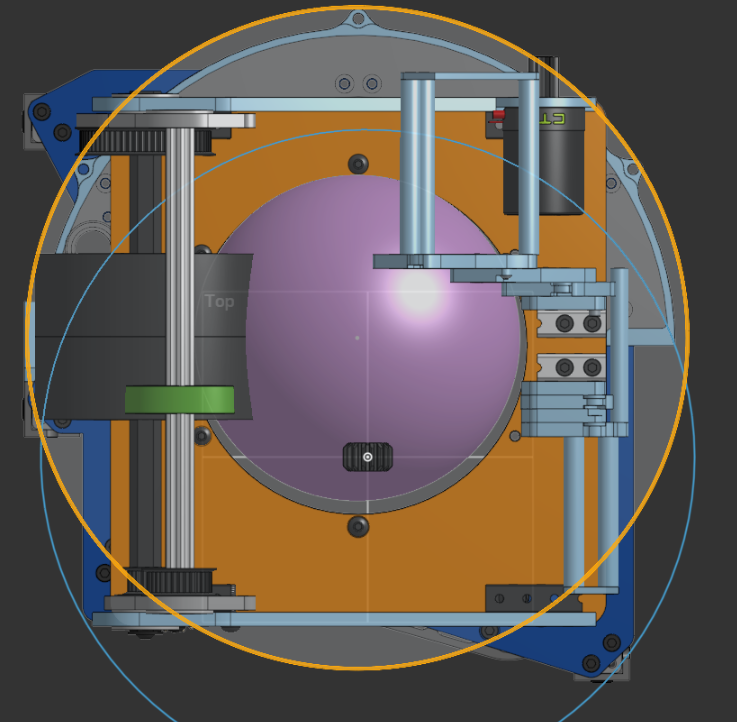
So, we came up with this!
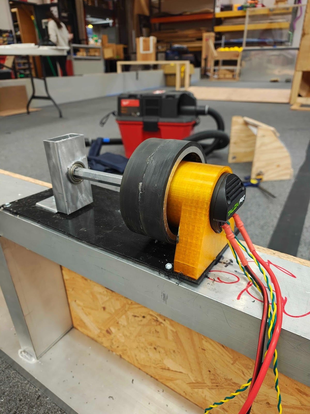
An internally mounted x60. Running it for over two minutes, at 10 volts, and feeding balls into it, we never went above 36° celsius, so we’re preliminarily considering it okay to use in a comp setting.
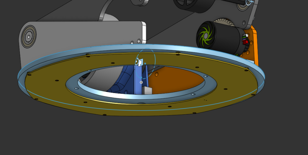
Putting in into context, here is the new (ROUGH) turret top:
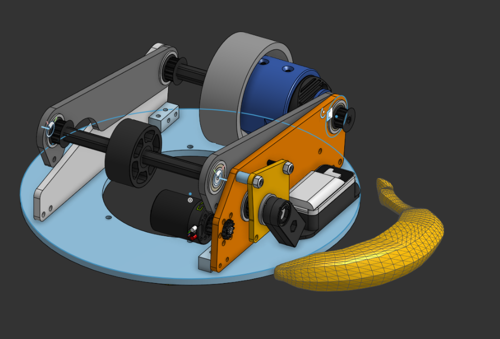
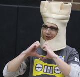
Banana for scale starts to look quite large when the entire thing is smaller than a 12” circle for a ~6” game piece.
Looking forward, we need to finalize the back 3d printed hood on the back, and simply put it all together since we’ve confirmed the prototyped 1:1 4” metal flywheel internal kraken x60 works, as seen above.
So, the mechanical assembly can rotate infinitely. But what about preventing our wiring from snapping off after we rotate too much?
This leads us tooo…
No more BIGUS:

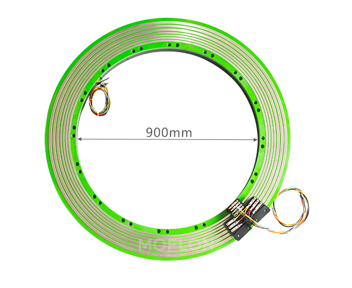
Why no BIGUS, you may be asking? Well, while a BIGUS (bi-directional energy chain) is great for managing wires on a rotating turret, it takes up significantly more physical space than a wire slip ring connector. A BIGUS system needs a full circular track plus room for the chain to bend and store extra cable length, which increases the turret’s footprint and adds mechanical complexity. But a slip ring is compact and mounts directly on the rotation axis, passing power and signals through a small, contained unit. Our design only requires a continuous electrical connection through full rotation, and a slip ring allows smooth, unlimited rotation, whereas a BIGUS setup would be limited and bulkier for the turret.
Here is an example of a Wire slip ring track:
If you want to design a custom slip ring–style power transfer system and remain compliant with FIRST Robotics Competition (FRC) electrical rules, the key is to size your conductors based on the maximum breaker rating feeding the circuit, not just the motor load. The wiring, connectors, PCB traces, and slip ring contacts must all safely handle the worst-case continuous current the breaker could allow during a fault condition. When determining how much current a copper PCB trace can handle, the two most important factors are trace width and copper thickness. PCB copper thickness is measured in oz/ft², meaning the weight of copper spread over one square foot. Standard boards use 1 oz copper about 1.4 mils thick, but heavier copper can be ordered. For this design, we assume 2 oz copper, which balances cost and current capacity. PCB traces don’t behave exactly like insulated wire, but we can compare cross-sectional areas. 12 AWG wire has about 3.31 mm² of copper area. Matching that with 2 oz PCB copper would require a trace 1.83 inches wide, far too large to fit four motor channels inside a 12-inch turret. Fortunately, we don’t actually need that much copper. Stranded wire contains air gaps between strands, and its insulation traps heat. In contrast, an exposed PCB trace benefits from better passive cooling, allowing higher current for the same copper area. PCB trace current ratings are based on allowable temperature rise above ambient. Using standard IPC-2221 calculators, and targeting a conservative 15 °C rise (40 °C max trace temp at 25 °C ambient) under a 40A continuous load, a 2 oz external trace must be at least 0.738 inches wide. We can further reduce size by sharing current between the top and bottom layers of the PCB and connecting them with many stitching vias. This halves the required width per side to 0.369 inches, which fits within our space constraints. For the brush contacts, we are using replacement commutator brushes designed for 4–7 kVA generators. Although intended for higher voltage systems, they are mechanically robust and capable of handling 40A continuous current, and they conveniently include springs and mounting hardware.
Here’s our currently in development custom one:
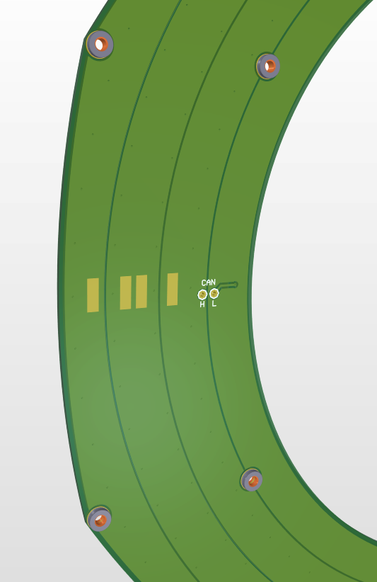
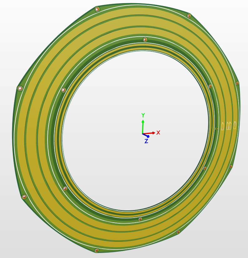
It’ll fit underneath our turret rotating assembly, mounting to some carbon brushes rigidly mounted to the frame, which we found on Amazon.
Intake/Index:
We have made a lot of progress assembling our roller floor and our intake.
First, for our intake, we got it assembled, and we realized that it was a little too floppy for our liking, so we added some rigid aluminum standoffs for more structure. And we attached the intake to the bot, and deploying the intake is a lot smoother. We also put belts on the intake, but we are waiting for some pulleys and belts to finish connecting all the pulleys. We got the floor roller indexers mounted and some of the belts in place, but we are waiting on those to come in to be able to link them all together. We also got our front 2 mini rollers attached as well. So, from the intake to the shooter, our bot has the entire floor with rollers to ensure constant feeding to our turrets.
The main thing stopping us from making more progress is parts… We are waiting for multiple orders to come in, then we can finish assembling and work out any kinks that come up.
Hopper:
Running on four bearings, located within 3d printed runners, it’s “mechatronics” like in how the motion is “programmed” through the rotation of the intake itself. We wanted a ton of free space at the bottom; however, to account for balls hitting the intake slightly up as they were intaken, and not cause the hopper to fold in. Overall, a simple design in practice, but a complex one in CAD.
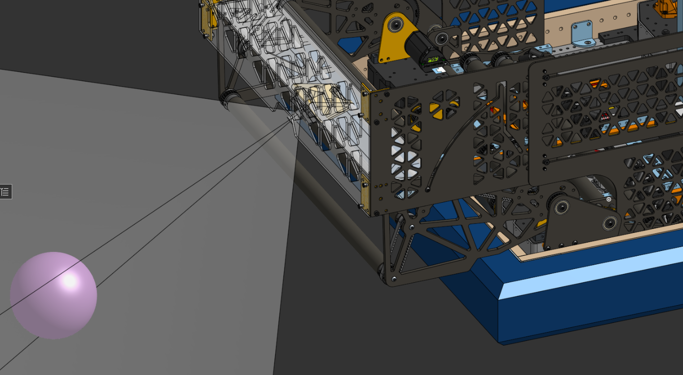
Hang:
The CAD is definitely CADding… in the past two weeks we've focused on making prototypes and finalizing our design. We re-mounted the hang so that the motors aren't glitching into the swerve modules in the CAD and it's actually… REALISTIC to build! The X44s? Out of the way. Throw a Maxplanetary on the other side connecting to that sprocket system, and BAM we've got that problem out of the way. We finalized the sprocket/chain systems on both sides of our hang so that everything was working smoothly (and within the confines of our allotted space).
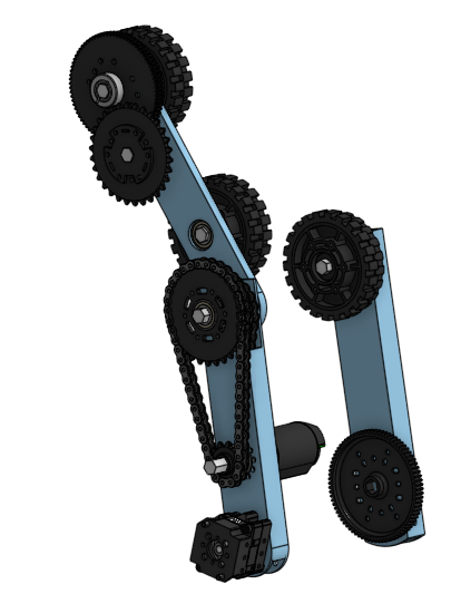
The hang currently looks like this. It’s only missing a couple of chains as well as a rework of the mounting on the right side as of early this morning. Overall, our strategy is basically to get those gear ratios as high as feasibly possible–we’re gonna need it if we want to roll our way up. We’re now powering it with all three of our remaining allotted motors, and currently the entire subsystem is “hanging” (get it?) at just around 8.5 lbs. Overall, this week we’re looking forward to actually starting to see this hang moving and grooving! Look for an update next week! (:
Wiring:
Over the last few weeks, we have been mainly focused on wiring up any subassemblies that winter storms have allowed parts to arrive for (not many). For most of the time, we spent working on the chassis, which turned out to be near perfect for us, as we were able to put many dedicated hours into wiring.

We have also been able to avoid grounding the chassis (for the first time in years) and get our CAN bus between the swerve modules working on the first try, so we’re quite happy.
Furthermore, we decided to use both the CANivore and RIO lines for our CAN buses. This allows us to do many things, but one of the main reasons is that when split, the CAN lines become more pliable and are easier to route cleanly. It also allows us to process things faster, since the RIO has slower processing compared to the CANivore. This allows our Mac mini to operate at its full potential for our detection system.
We also decided to use two MPMs (Mini Power Modules), not out of preference, but mainly due to the large number of components that require their smaller WAGO connectors. Another choice we made this year was to step nearly entirely away from Anderson connectors (Powerpoles, quick disconnects, etc.). This was mainly because they are difficult to assemble and have a tendency to fall out without the retaining clips, which we unfortunately do not have. Instead, we made the wires one continuous run that goes straight from the PDH (Power Distribution Hub) to the Krakens. We are able to do this because the Krakens have small terminal screws that allow wires to be easily removed and reinstalled, unlike the NEO motors, which do not have this feature. This resulted in significantly improved organization of our robot’s wiring.
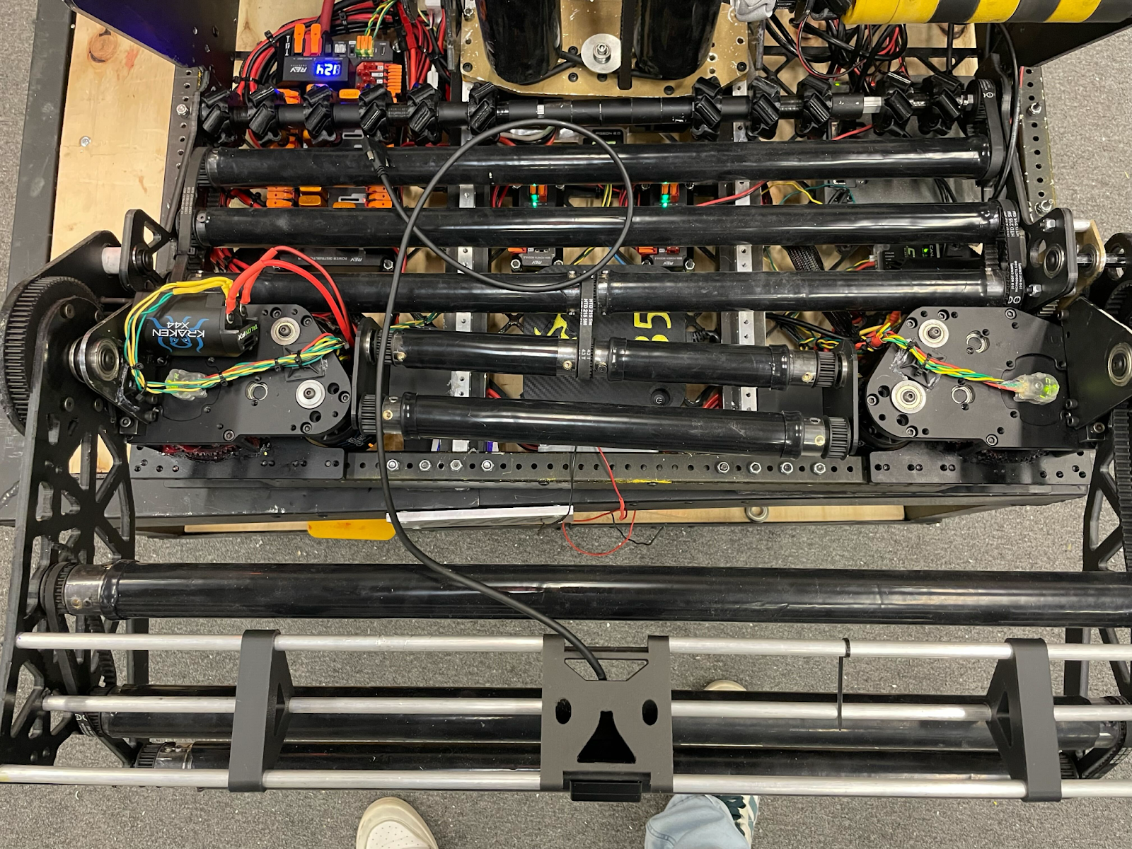
So that picture may not look like much, but we’ll break down the problem. (With advice if you’re struggling, read this; it might help, it might not.)
- So if you look in between rollers there is a clear distinction between CAN paths and power paths this is because of interference and while negligible sometimes it still isn’t great this is due the frequencies bounce back off of the power line due to magnetic fields formed by the positive and negative lines which interfere with the CANs frequency so it is best to keep them apart.
- Soldering is good (sometimes) now with can line Wagos, which are often very repairable it creates a lot of unnecessary resistance and weight so we opted to solder this year, which so far has gone very well with no CAN errors, knock on wood, and CAN be done easily so first strip about ½” to 1” on both wires you are trying to solder together then do not forget the heat shrink as that is very important for the wire to not interfere with itself then you line up the wires at about the midpoint of each then twist together and the point should be fairly strong then add enough solder but do not overdo it as you’ll make it too thick for the heat shrink to fit over the wire then put the heat shrink fully over the solder point and heat it up (typically done with a heat gun)
- Organization now this part is kinda subjective and doesn’t require much typically you want as little touching of Can and power as possible this can be done with loads of different tools such as the humble zip tie typically these are cheap easy and look half clean so this is what we opt for though i’ve seen wire holders like with the screws or nails but those typically weigh more but are more durable and some form of a shell around the wires (wire loom, snake skin, etc.) these are optional but I would recommend in areas such as a lift though this year i doubt we’ll be seeing much of those.
- When connecting to PDH we found it better to use just bare stripped wire but be absolutely POSITIVE that the no wires touch as the outcome would be quite NEGATIVE for your team (also red is positive black is ground) this includes frays so make sure to twist wires and if the problem continues to fray then simply solder the bare end and you’ve pretinned it no more fraying. Now this all may seem GROUNDbreaking at first, but this is decently easy to memorize and is basically common sense (we definitely had wires fraying and touching
- Then for our rollers on the bottom they’re supposed to fold up (they definitely did not do that) for easy access of wiring this is very important for this years game more than other years prior due to the amount of defense that will be played causing an eventual failure somewhere (unless it's perfect though we're doubting)this allows for quick pit repairs to be possible
- Tension in wire equal bad very bad as it is pulling on everything its attached to make sure to leave slack on some wires when necessary such as our roller motor as its supposed to flip up (it can do it at like a thirty degree angle then hits something) we prolly left 6 or 7 inches of extra slack on it just GAUGE it by holding the wire where it needs to go and figuring out the longest distance then cut the wire to typically have two to three extra inches.
After this, you're probably wondering how in the world this guy's wiring work first try. We don’t know, but this is what we hoped. This helps
Though there's still more ahead of us (turrets)
Programming:
Our programming for the robot has been shockingly quick for this year's game, given that we had expected a game including a complex pose system for pick-and-place behaviour, and did not need it. However, through the backend development of that system, our swerve, vision, LEDS, arms, rollers, and climbers all of those systems had to become more efficient so that more complex code could be run in 20ms cycles.
Therefore, for this year's game of “Go to neutral zone, pick up, feed teammates/go back to Alliance Zone and score”, we barely needed to do any true “programming” at all, only refactoring implementation… besides the Turret Math (which is public at here)
Furthermore, here is our robot code once more.
Here’s our controls, running a singular driver system on an Xbox Elite controller.

The megolovania play command is EXTREMELY important for the robot’s proper function.
The code is all public, please feel free to dive in and analyze the unique ways we go about “Jackhammering” and “targetting” trenches in the code itself.
Our turret code works, having the turret rotate and unwind itself as it gets radians, however, that might not even be necessary given the new turret design… (we love programming while designers CAD...)
Let the Machining Commence!
Our design team has been cooking, and the time has finally come to start making parts. Lots of parts. We didn’t mention machining our chassis rails, but they are pretty standard stuff, 1x2x.097 inch 6061 aluminum with a half-inch hole pattern, 1 row on top, two rows on the sides. Cut, machined to spec, deburred, powder-coated, and assembled. The four Thrifty narrow swerve modules completed the overall frame, and we added two 1” x 1.5” aluminum bars to help reinforce the chassis with custom CNCed brackets to hold it all together. Some rivets complete the assembly. Speaking of reinforcement, SRPP cutting commenced!
We went through, cut some test circles, verified our laser feeds and speeds, and got to cutting the belly pan. Three hours later, our belly pan emerged, and our laser. Well… as the saying goes, didn’t cut it. After an agonizing hour of jigsawing, bandsawing, cutting, and deburring, our FINISHED pan emerged. An aluminum plate in the middle ties it all together, and gives us a perfectly rigid (and centered) mount for our Pigeon, as well as the rest of the required electronics and the brains of the Oracle system - the M4 Mac Mini. From here, the chassis went to wiring, but the machining had only just begun.
Not to be defeated by our laser, we started messing around with speeds and feeds to cut the SRPP on the router. It is a bit slower, but our results have been great with Carbide - 15,000 RPMs, 50 IPM, go BRRRR. Brackets, intake parts, turret kicker side plates, you name it. The router has also put in a 40-hour work week.
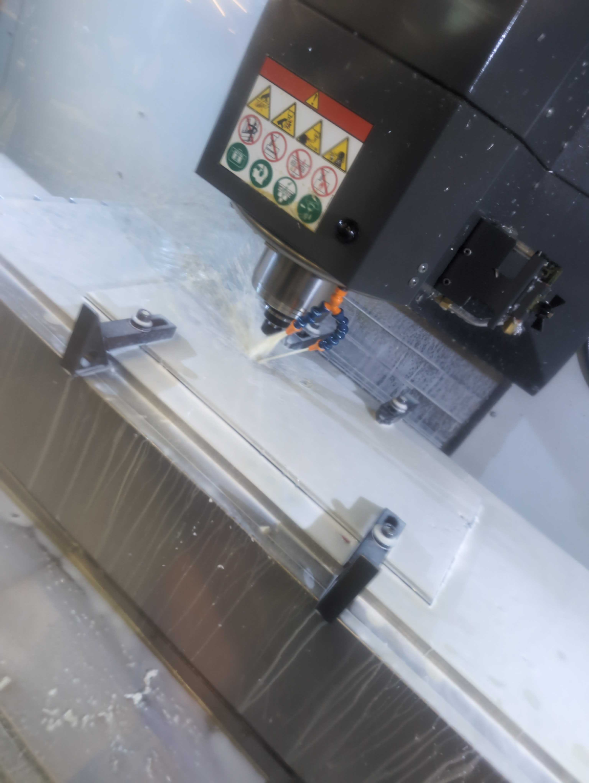
For the delicate aluminum machining, we turned to our trusty Haas TM-1P and our stock of aluminum. The miter saw roared across the lab, cutting stock to size in all dimensions. A lot of it is standard fare, tubing with bolt patterns. But then, we started making nut strips - 36” long bars of .5x.5” aluminum with holes drilled every half inch, then flipped 90 degrees, and drilled again with a .250” offset, and each hole tapped. We tapped well over 800 holes this week, but the nut strips solve many problems - no overtorqueing and crushing thin wall tubing, single tool maintenance, as we no longer need wrenches to hold the nut, similar weight, and, best of all, fewer holes. Everywhere. The options are truly endless.
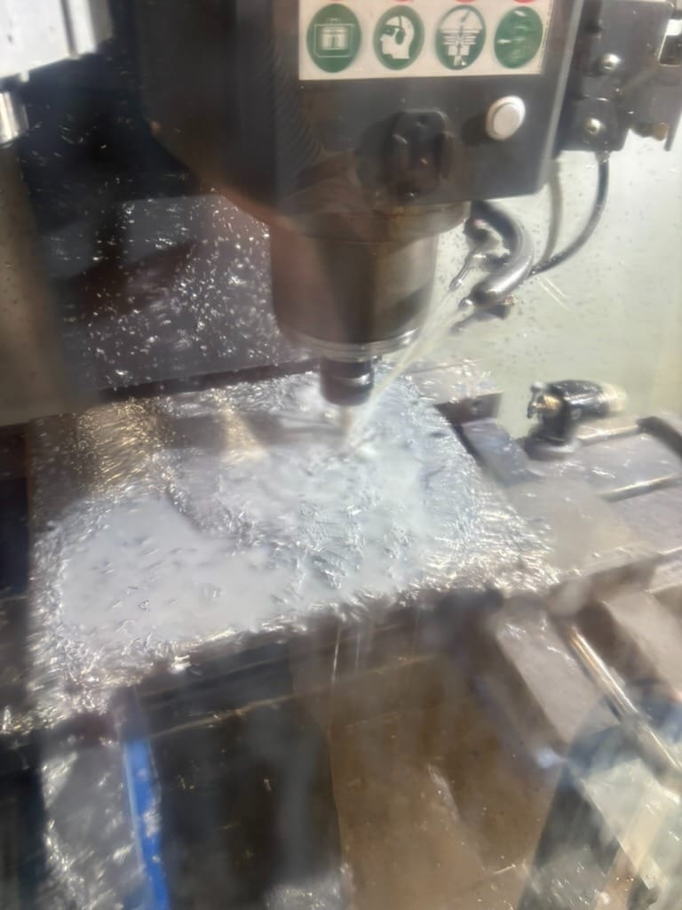
Our most Ambitious Project of the Week award is a toss-up - we had two parts this week that tested our students, mentors, and patience - a 77-tooth 10 DP gear for our turret, and the turret mounting plate itself. Both were machined out of .250” thick 6061-T651 for maximum strength, but each came out of a 12” wide plate. We mounted it expertly to a half-inch piece of plywood, clamped it in our jaws, and sent it! Small issue - our Haas only has 12” of travel in the Y, so when we went to probe, we had issues.
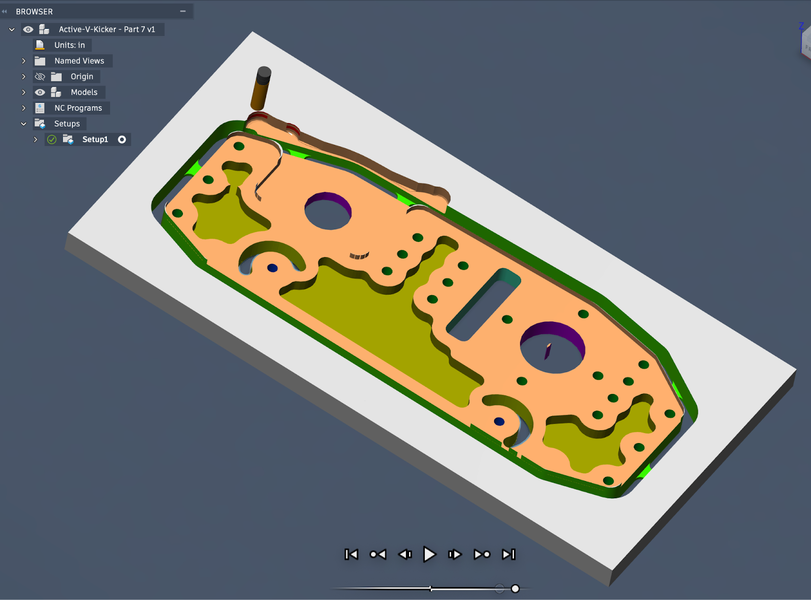
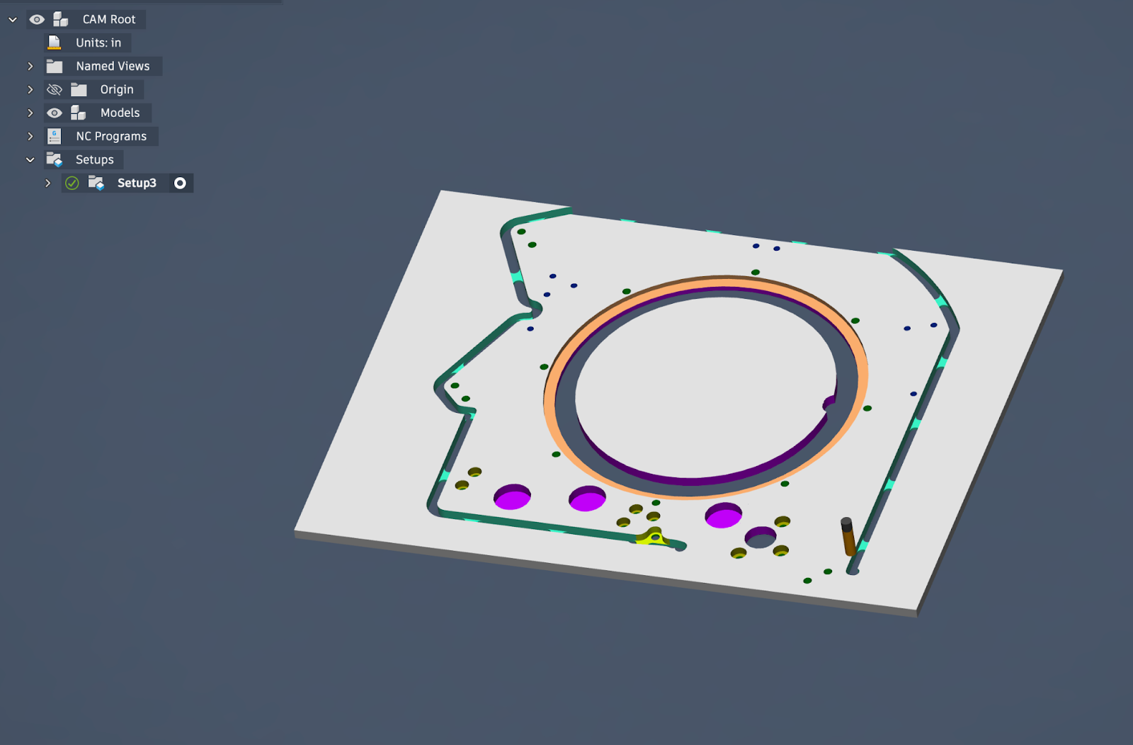
So, we busted out the trusty eye-crometer, set our zeros, and started cutting. All went well on the first gear, holes drilled, centers punched, and one cut out. We went to machine the second gear, and were over travel limits. Many CAM changes, tricks employed, all to no avail. And somehow, our .125” endmills (which are OVERSIZED) for the root of the gear just started snapping. New one in, slow the feeds.
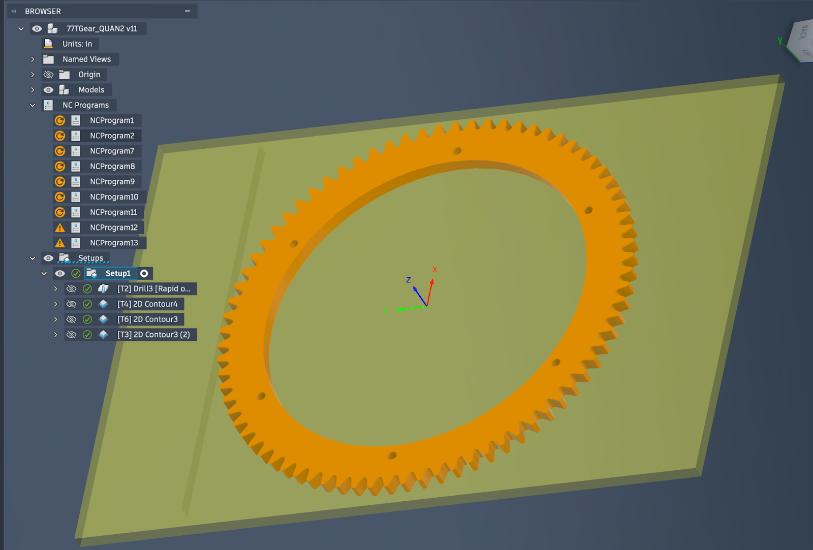
Snap. Change depth of cut to shallower bite - break. 5 endmills later, we FINALLY got a gear out, but the roots were TERRIBLE. After this, we reached out to a mentor and asked about a waterjet job for this integral part. We got plans aligned, and the day before we were scheduled to cut, the waterjet crashed and was out of the picture. He figured out how to make the gears more effectively on his much larger Haas VF-2SS with a pallet table, and now, we have three more perfect gears.
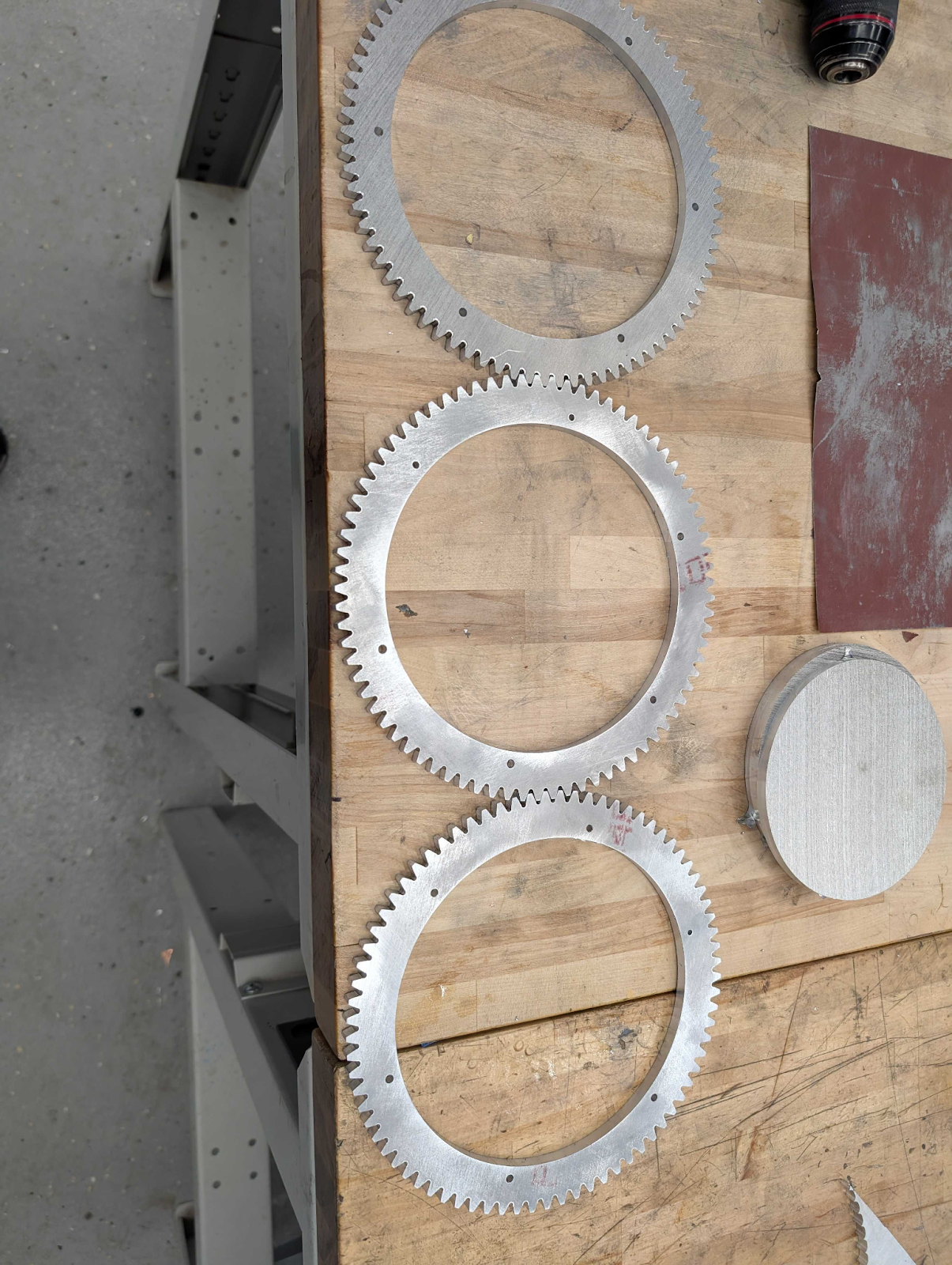
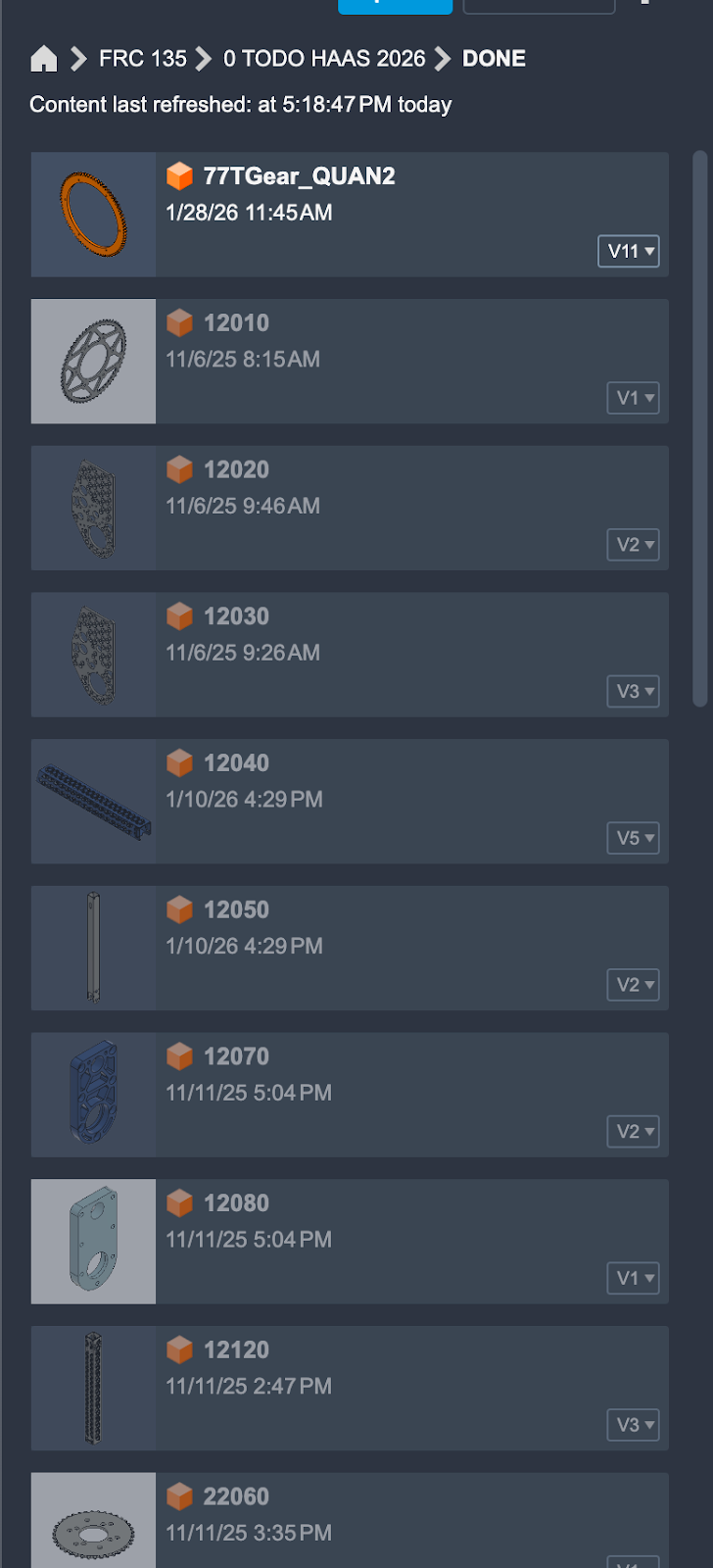
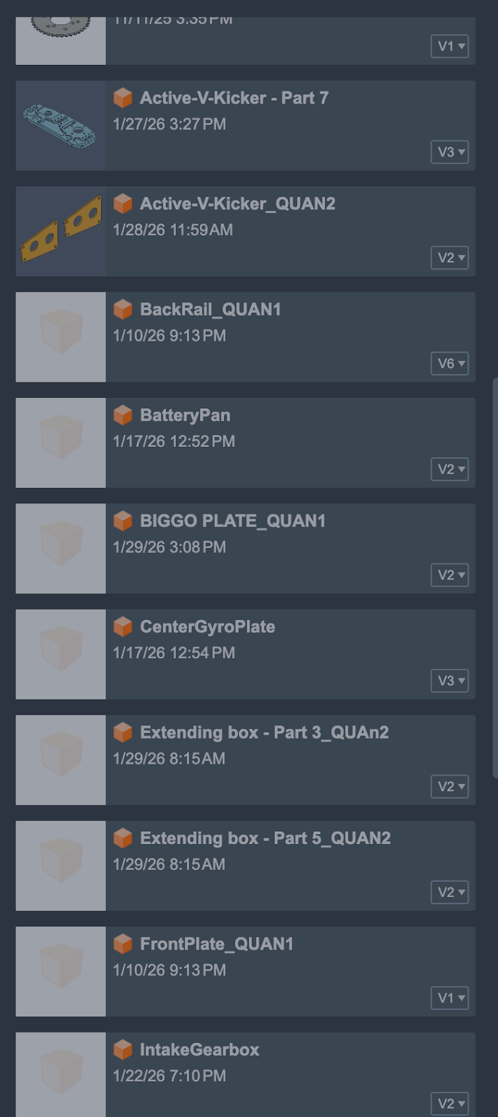
Overall, lots of machining this week, obviously. We haven’t even talked about the lathe work, which there was a TON of. Or the 3D printing. There were two tons of. But the To Do folder is empty, and the Done folder is bursting. Every part, made in house, deburred, powdercoated, inspected, and sent to assembly, which is where we sit now. Waiting on literally 9 - Seriously NINE - bearings to complete the assembly from intake to turrets.
Go Black Knights!