Update - 1/19/2026
Design and Assembly Week #1 Update
Buckle your seatbelts because this bout to be long.
Turrets (yes, turretS)
First, we needed to confirm the math behind our turret shots and find the difference between no hood and hood… But before we can do that, we need an FPS range we’re going for on the ball. Looking at Ri3D’s and our own analysis of the game piece and its weight/material, finding that we’ll need anywhere from 18-26 FPS. That means around a 3:1 ratio on a Kraken x44 FOC running in FOC within its torque band, using a 4” flywheel. (This math is trivial to do once you have the desired ft/s).
Looking to the FRC 2022 Trajectory Calculator for a general angle solution, that means we need anywhere between a 12 degree angle on the hood, and 30 degree angle. HOWEVER, there’s a strategy our team has found to be worth it, especially with two turrets.
Shooting into our trenches.

Shooting to your teammates is something we predict will be able to swing matches, as we’ll be able to feed our teammates accurately while poaching from the opposing alliance and or being the only robot in the neutral zone. To that end, we’re actually going to need to get to a 50 degree angle on the hood, so an overall ROM of 38 degrees.
Now, after looking further at Ri3D’s, specifically Penn State’s shooter testing, having SOME backspin will be nice for these balls, but not too much since we want to feed our teammates. So, preliminarily, we’re simply going with 30%, otherwise known as around a 1.7x difference between top and bottom rollers if the top is 2” and the bottom is 4”.
And last but not least, feed speed.
Getting it up there with speed is going to be way more important in our opinion than having two motors on the flywheel, especially as we’re within the torque band AND it’s a 3:1 ratio. Feeding at only 3ft/s allows us to go from around 90ms in the shooter to 20ms, and that isn't just a 70ms decrease in "reprime" time, it's also less force overall, higher efficiency, etc. Very worth it.
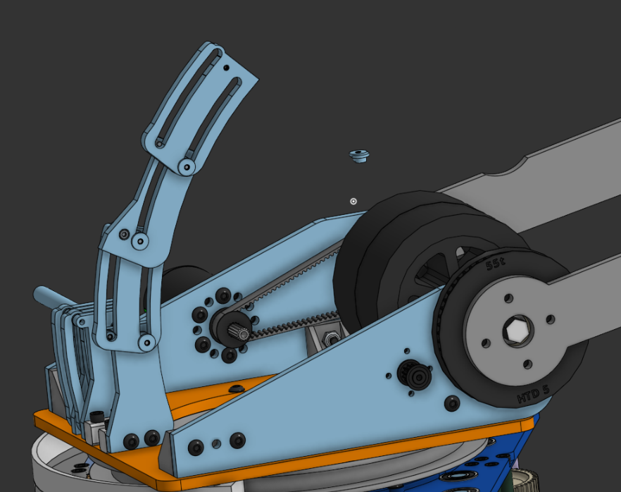
HOOD CHANGES!
The V1 turret has been made and there are already some changes due. Currently, the turret is very illegal by the fact that it can barely turn without breaching the robot perimeter, and the design is kinda just clunky.
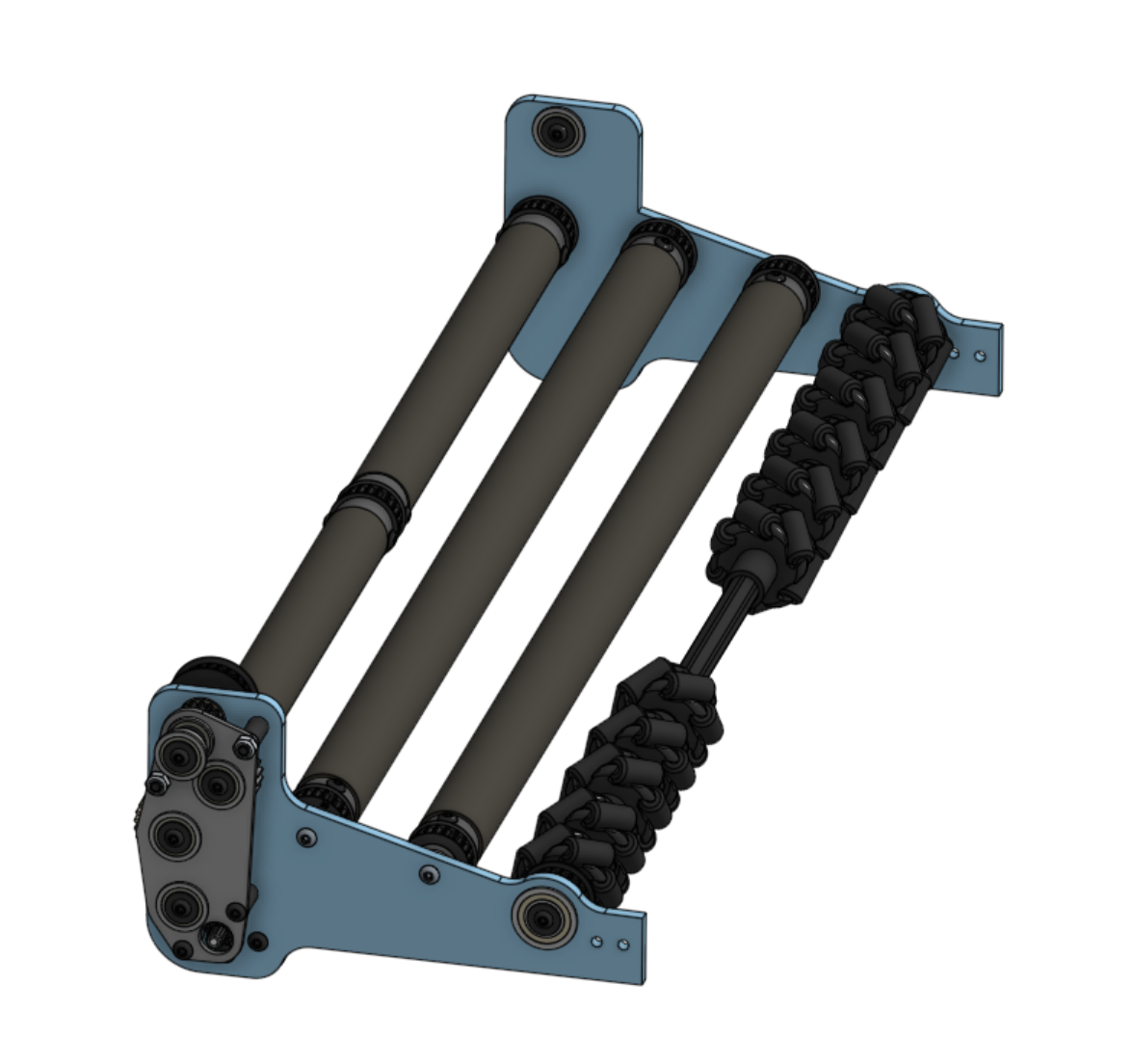
So… what went well? The most important thing that worked was the cascading hood. I don’t even know how many revisions I went through before I settled on this one
Pretty cool eh?
Originally, the design ran off of a single pin per stage, but that did NOT work. The stages would just spin around when pushed down on.
What needs to change:
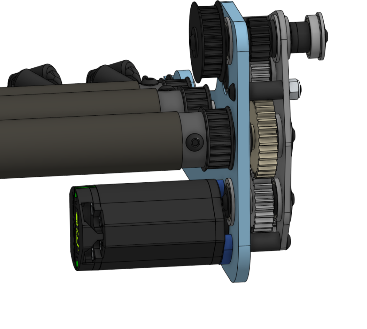
Motor positions- Currently, our flywheel motor is being driven by a Kraken X60 that sticks directly out of the bot (as kinda seen in the picture). The problem with that is that the motor very quickly goes outside the robot's perimeter with any rotation. Our solution is to keep the 3:1 ratio but instead run the motor at the back of the turret, next to the hood. It’s going to be tight, but it should work (hopefully)
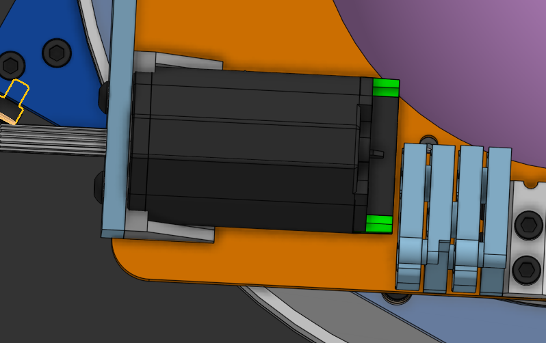
Test fit is TIGHT but it might work
The neo 550, or soon to be Minion, is also in a bad spot because there is no realistic ratio that will work at that distance. Our solution to that is to simply put the motor at the back of the turret and make a gear train. The math tells me that a 20:1 should be sufficient with a Minion, while a 550 is going to be at some crazy ratio like 80:1.
Nut Strips! - Grant loves his nut strips, so instead of my totally rad 3d printed brackets, I’m going to replace them with his boring aluminum poles. I guess they are going to be “more compact” and “stronger” or something 🙄(JK Grant nut strips are better in this case)
Basic changes- Just minor tweaks here and there need to be done to bring this from an idea to a real, official part. Those will be more of an “iron out on the way” thing though.
Main Roller Feeder
We’ve been looking at a way to continuously move the large number of balls from the intake to both turrets.
The 4 main things we want from this indexer are:
- Maintain ball movement at all times
- Be as wide as possible (to fit more balls)
- Be able to outtake or vomit out the front of the bot
- Allow for easy maintenance
We are continuing to play around with the best geometry for balls to intake but also outtake. It’s a tricky slope (get it), trying to find the right angle for the balls to get pulled up the rollers.
Here's a video of some early prototyping: Link
We are planning on putting some raised bumps of some sort, whether that is some simple zipties or special custom wheels, to help move the balls and keep them from getting clogged.
We are also proud of our use of a zombie axle. In order to check off #4 from the list above, we need this thing to move out of the way of our electronics. We are doing this by using the top axle of our gearbox; we are able to pivot the entire assembly to give us access to any electronics below.
Preventing Jams and the Vindexer
What we’ve considered to be the most likely to fail component of this robot is how we turn our streams of balls into the turrets, from the main indexer and hopper. So, we’re going with the idea of “if everything’s active and has sensors, we can always jackhammer different motors to untorque the balls.”
This is the Vindexer, which turns one stream of balls into two. Using mecanum wheels to segment the center, as well as (in contact by .5”) bigger silicone rollers forcing them to the sides, as well as more mecanum rollers from the normal indexer on the bottom (not in the Vindexer CAD) Currently, the spacings between the rollers and the side rollers is simply at a length that we have belts in-house for, so we can test the whole subsystem handoffs faster.
For those who simply want the numbers, the top compliant wheel is in contact with the ball at ~.5”, the silicone roller at ~.5” as well. Using a twisted belt, we were able to make the battery fit behind this assembly, and give us space for a vertical belt to run from the bellypan to the top shelf roller. All of the wheels in the Vindexer are running at a 5:1 ratio, but we might change that to a 4:1 or 3:1; we’ll see. At the 5:1, we’re expecting around 5-7 ft/s up to the turret, which (as discussed above) is more than enough.
We’ll need to find out where we want the kickup rollers on the back to be, but given that we already have a pulley with a 5:1 ratio accessible (see the top axle currently open), we don’t see any packaging issues conflicting with the turret at all, and we plan to base it off of Cranberry Alarm’s numbers, since they worked well. It is a V1, after all.
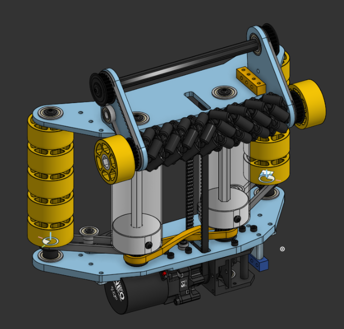
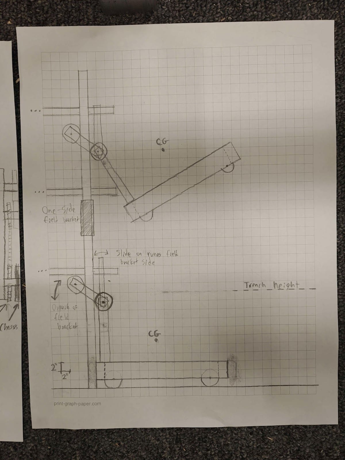
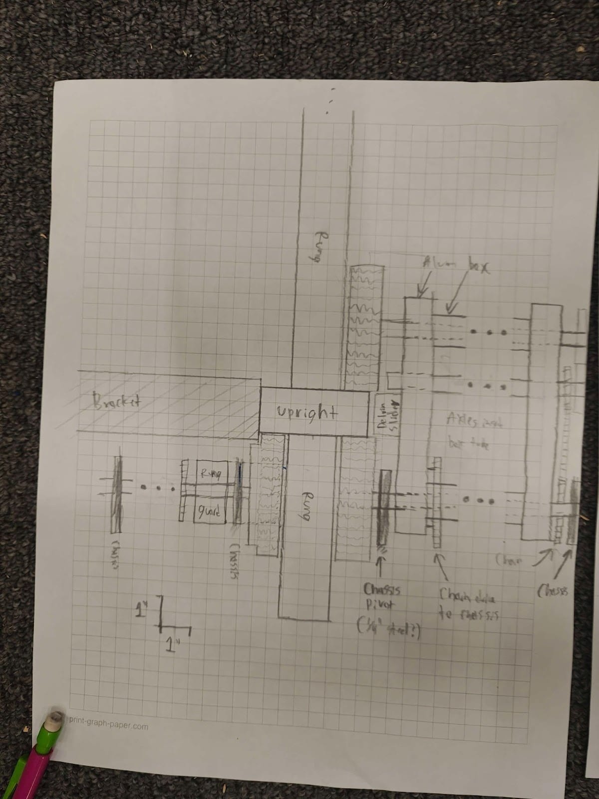
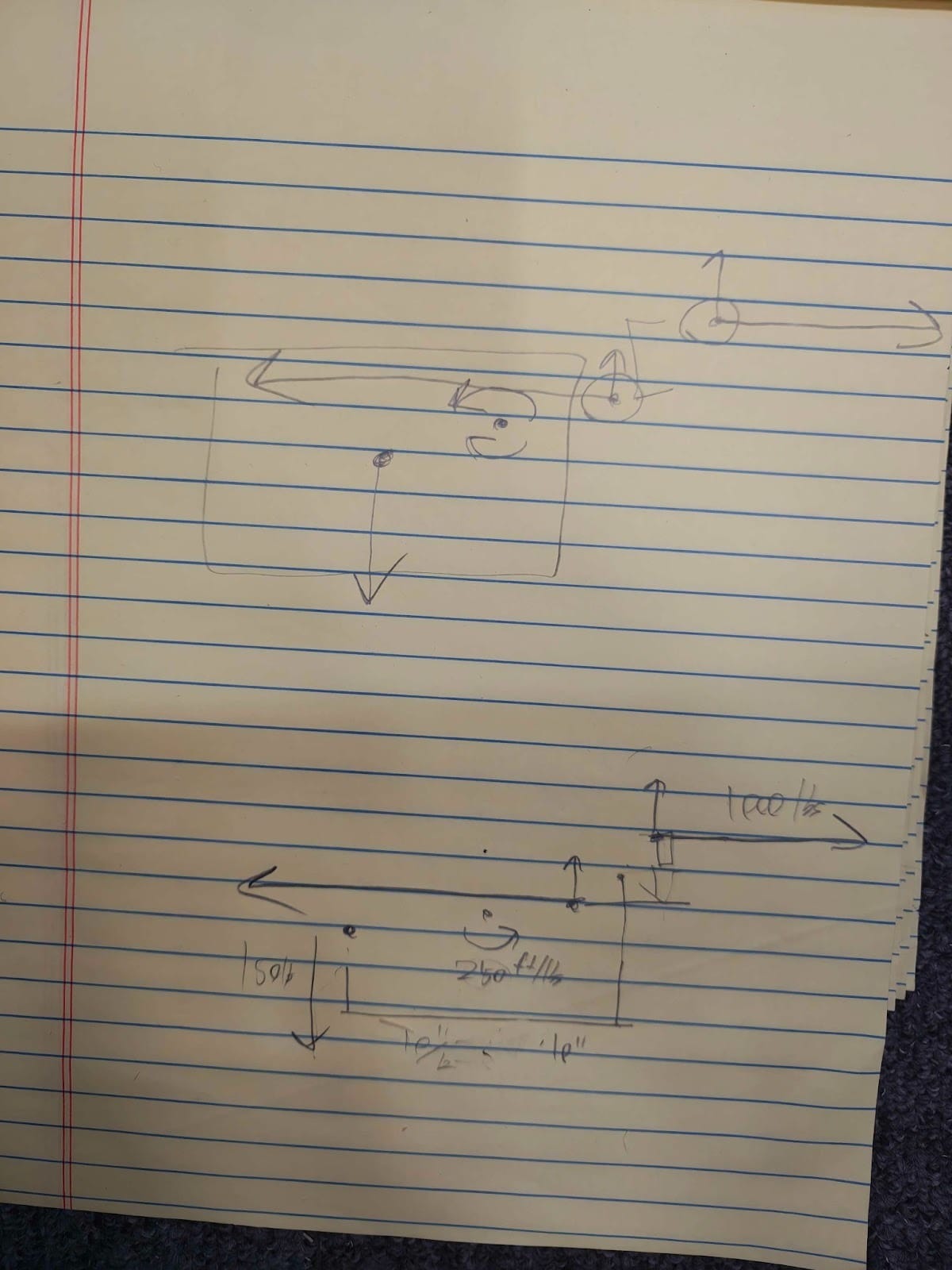
Hang (part 2)
Three different hang ideas and half a prototype (if you can call it that) later, we have a hopeful path and a unique solution. Our main goal is to blow up and act like we don’t know nobody stay out of the way, and on the sides of the tower. So, we’re choosing to essentially roll our way up the sides.
So our plan of attack became physics. About an hour of calculations later, we figured out that it was possible–but we’d have to be precise. Here are the basic sketch ideas, as well as the rough math that we did to figure out if this was feasible.
PART 2: CAD
After our sketches, it was time to go straight to Onshape and model this three-dimensionally. After some time, we ended up with this:
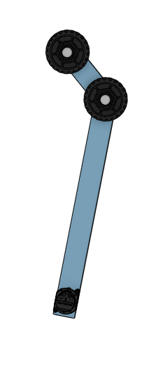
(top view so you can see that sprocket system!)
The end effector is sprocket and chain driven. A Kraken X44 at the bottom drives an internal sprocket system, with a chain reaching up to another internal sprocket at the top. This allows the arm to pivot, helping us to both climb and stay in frame perimeter. When it’s time to climb, the motor simply spins the end effector out so that it’s ready to climb. The rest of the time, it stays inside the frame perimeter. This definitely isn’t the final iteration, and we hope to create a physical prototype of this shortly (debate took me away from this beautiful idea over the weekend) so that we can actually ensure its functionality before we throw it on the robot for sure. Check back soon for that physical manifestation!

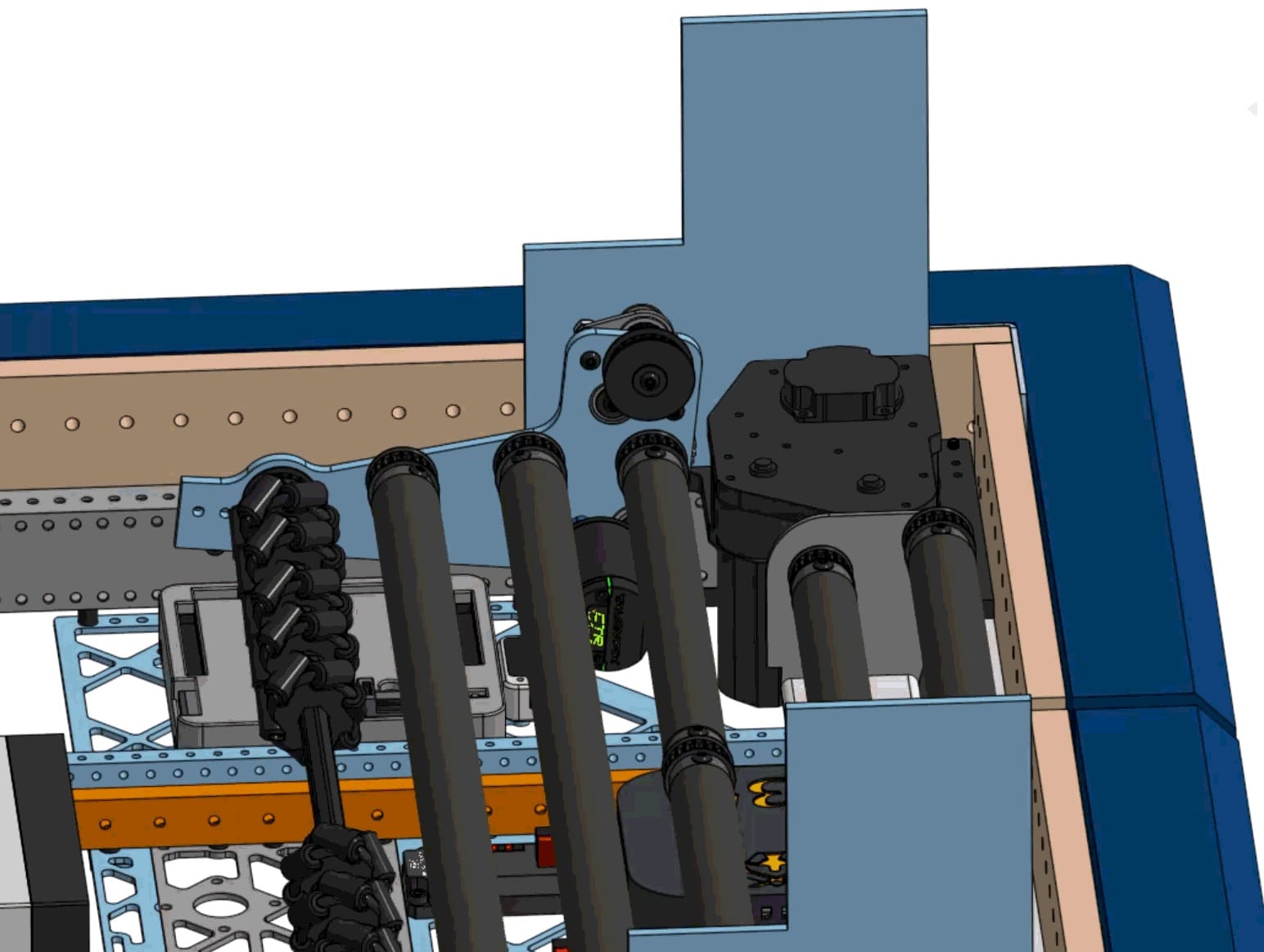
BIGUS
Bidirectional energy chain or BIGUS, is a way of storing and managing wires, allowing them to rotate in both directions around a turret without getting jammed or snagged from foreign objects. It also minimizes the space needed for wire management.
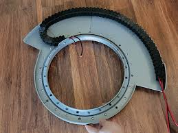
The image you see below is a top-down view of the turret. Here, the BIGUS ring goes around the outside of the turret, which creates a controlled path for the wiring to warp and unwrap smoothly while the turret rotates in either direction. The design you see here only allows for 180 degrees of full rotation, which is more than enough for what we need due to our double turret design.
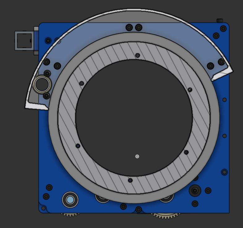
If you plan on doing BIGUS, make sure to get an energy chain that is able to actuate/rotate both ways. There are a couple of sellers that have these types of energy chains, like West Coast products, Igus, or Cable ties and more. There are also free STL files that you can get on Printables.
Looking Forward
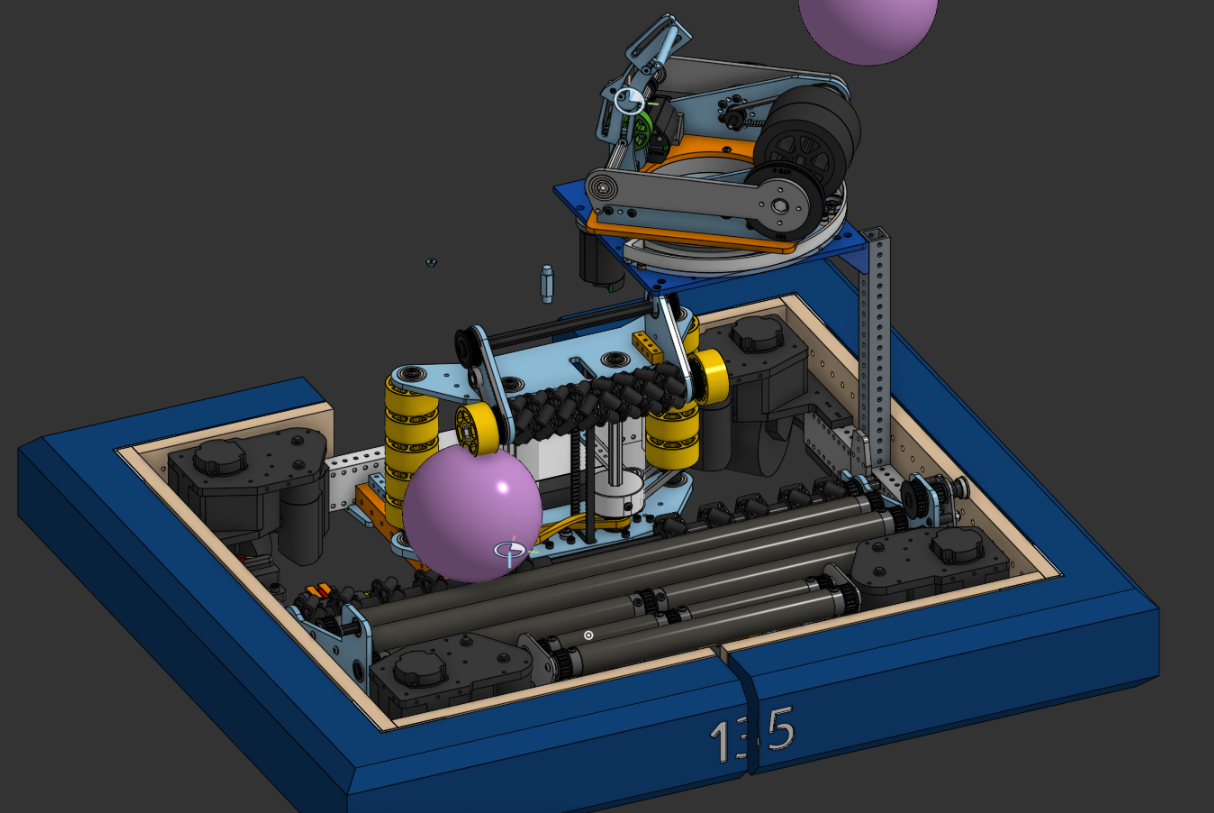
This is our overall CAD so far, besides the hang, which would be behind our Vindexer. We’ve tested out the main indexer and have changed it to what we noticed in real life. Looking forward to what's to come this week, we’ve already machined quite a few parts for the indexer and Vindexer, and we’ve got many more orders from the relevant suppliers.
We’ve already got bumpers and drivetrain done, but we’ve yet to mount the electronics in their relevant spots or wire it all up cleanly… nor have we mounted the bumpers with our pneumatic fittings “inspired” from team 5000.
We have so many parts left to assemble…
Go Black Knights!